Spectral Dynamics Probe
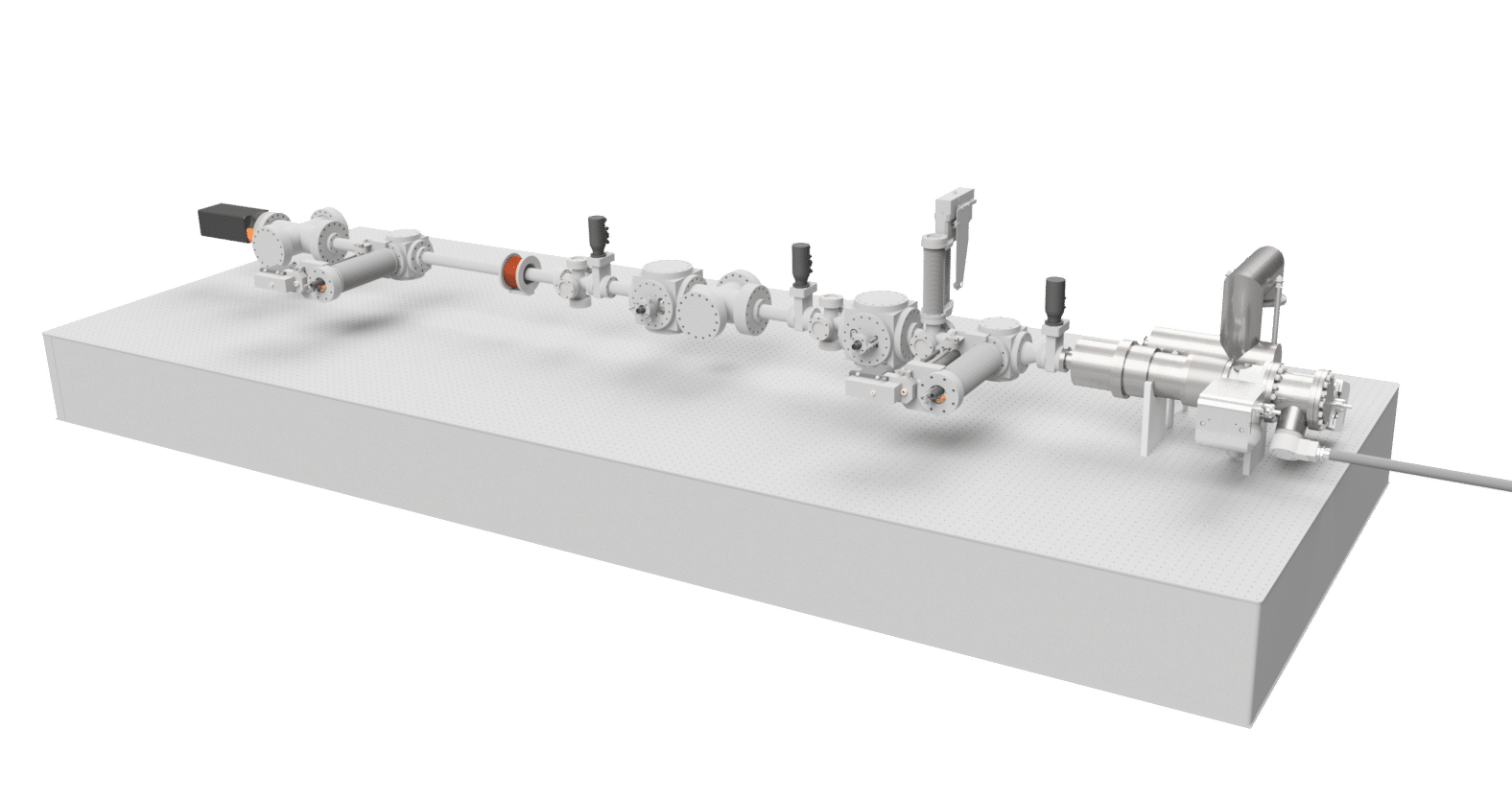
The Electron Energy Loss Spectroscopy (EELS) system is based on time-of-flight (ToF) measurements of the kinetic energy lost by electrons interacting with a sample. The ToF EELS system consists of two deflection cavities and two compression cavities. First a deflection cavity produces a pulsed beam by chopping a continuous beam from a high-brightness electron source. The electron pulses are then sent through a compression cavity which imposes a positive velocity chirp on the pulses, thus resulting in stretching (instead of compression) of the pulses in the drift space behind the cavity. Due to stretching the uncorrelated energy spread of the pulses is reduced. The stretched pulses are sent through the sample. The energy loss suffered by the electron pulses is subsequently ‘longitudinally imaged’ in time by the second compression cavity by imposing a negative velocity chirp on the pulse. At the point of maximum compression, the ‘longitudinal image’ point, the second deflection cavity is positioned, which streaks the pulses across a detection screen. All four cavities have to be fed by microwave signals derived from the same oscillator so that they run exactly in phase. If a continuous electron source of sufficient brightness is used, e.g. a conventional FEG, 25 meV energy resolution can be achieved in combination with 3 ps time resolution. For more information about the crystallography system please consult our white paper or contact us.
FEATURES
- meV energy resolution
- ps time resolution
- RF based dispersion
- Field emission gun
- Robust
- High throughput
SPECIFICATIONS
| Beam energy | 30 keV |
| Energy resolution | 25 meV* |
| Temporal resolution | 3 ps* |
| * simulated performance |
This System Contains
Field Emission Gun
A 30 Kev Field emission gun produces a high brightness electron beam with an energy spread of, typically, 0.5 eV.
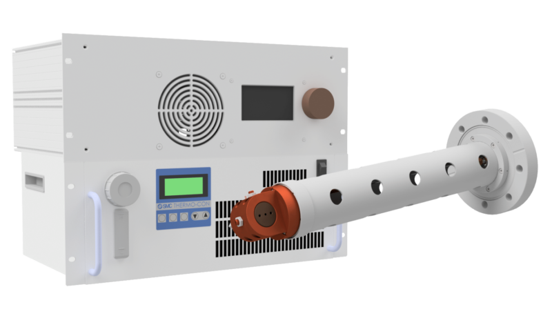
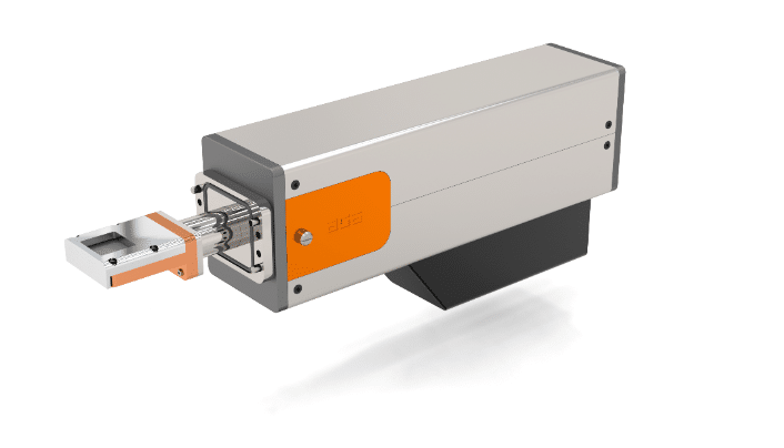
Deflection unit
Deflection unit is used for chopping the DC gun into ultrashort pulses. This is done by sweeping the DC electron beam across a slit. The deflection unit consists of a RF cavity which operated in the TM-110 mode. The cavity is driven by a 15 W microwave driver that also contains a feedback system which stabilizes the phase and amplitude of the fields in the cavity. This is made possible by a pickup antenna which measures the fields in the cavity. The unit is equipped with a temperature controller which keeps the cavity at the desired frequency so that all applied RF power is absorbed.
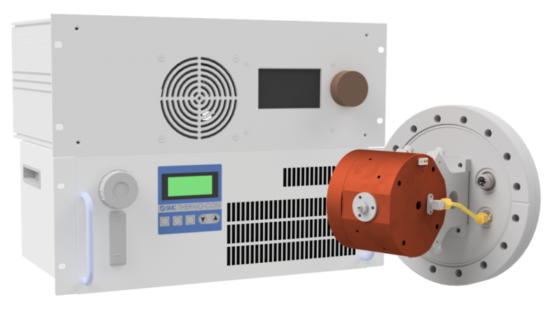
Compression unit
The compression unit is based on a RF cavity which is operated in TM-010 stretching mode, adding correlated energy spread to the bunch. This is done to enable an energy resolution better than the source energy spread. The RF cavity is driven by a 100W microwave driver that also contains a feedback system which stabilizes the phase and amplitude of the fields in the cavity. This is made possible by measuring the fields in the cavity using a pickup antenna. A temperature controller keeps the cavity at the desired frequency so that all applied RF power is absorbed.
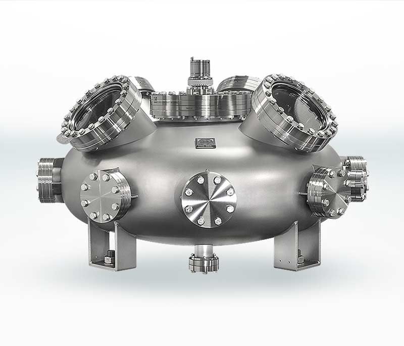
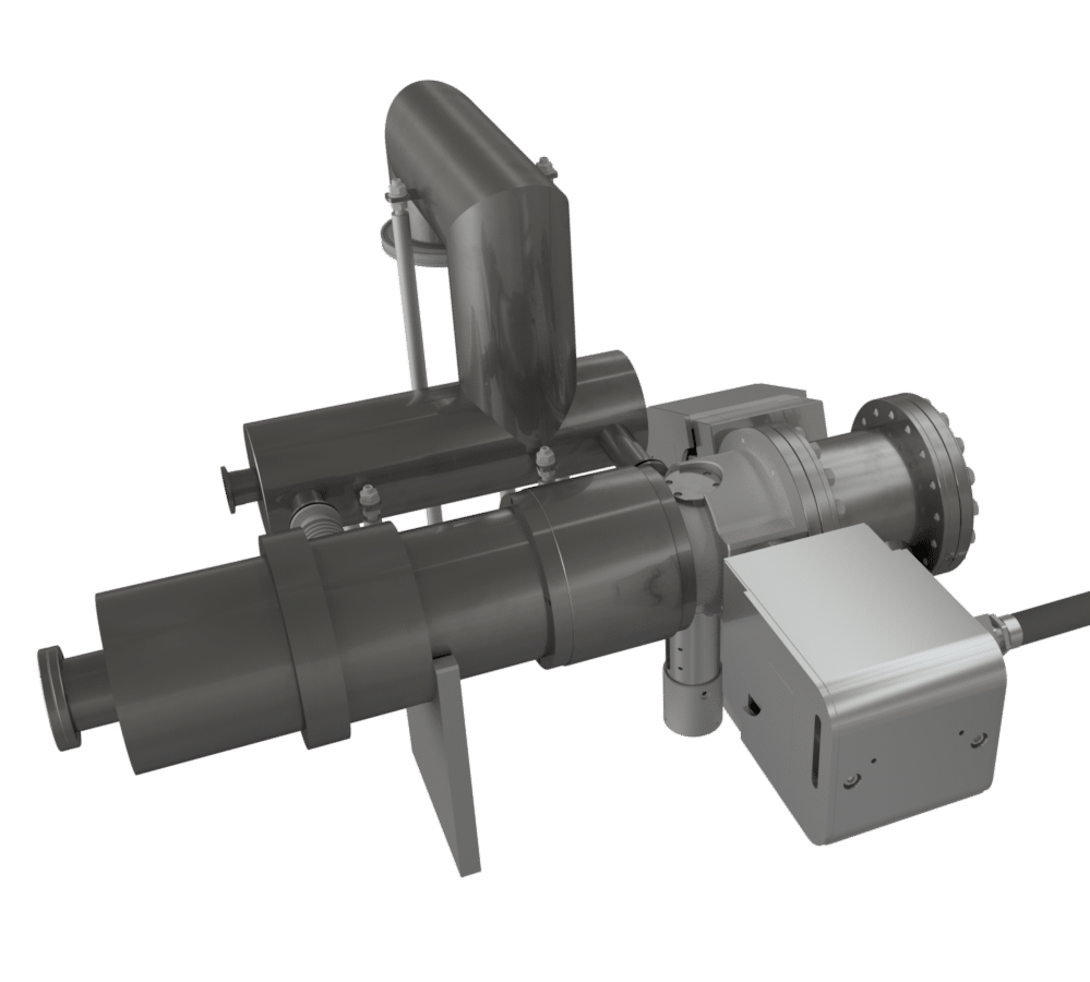
Sample chamber
The electron pulse interacts with the sample in the sample chamber. This chamber preferably has multiple ports for diagnostic tools to be inserted. Here one can think of a deflection cavity to measure pulse length of the compressed electron pulses at the position of the sample. Custom sample chambers are available on request. Please contact us for more information.
Compression unit
This cavity compresses the electron pulse with a temporal focus at the center of the final deflection cavity. The compression cavity is driven by a 100W microwave driver that also contains a feedback system which stabilizes the phase and amplitude of the fields in the cavity. This is made possible by measuring the fields in the cavity using a pickup antenna. A temperature controller keeps the cavity at the desired frequency so that all applied RF power is absorbed.
Deflection unit
The deflection cavity sweeps the beam across the detector. This results in a streak that converts the energy loss to a position on the detector. The cavity is driven by a 15 W microwave driver that also contains a feedback system which stabilizes the phase and amplitude of the fields in the cavity. Also this unit is equipped with a temperature controller and a pickup loop.
TimePix detector
To detect the electon bunch that has diffracted from the sample we recommend a hybridy pixel camera such such as the TimePix3 from ASI. ASI is the world leader in hybrid pixel detectors and offers state-of-the-art camera systems based on Medipix and Timepix technology developed in collaboration with CERN. These cameras have a 2D array of smart pixels that can measure the energy of an incoming charge. The cameras can be custom built into many different experiments for multiple applications.
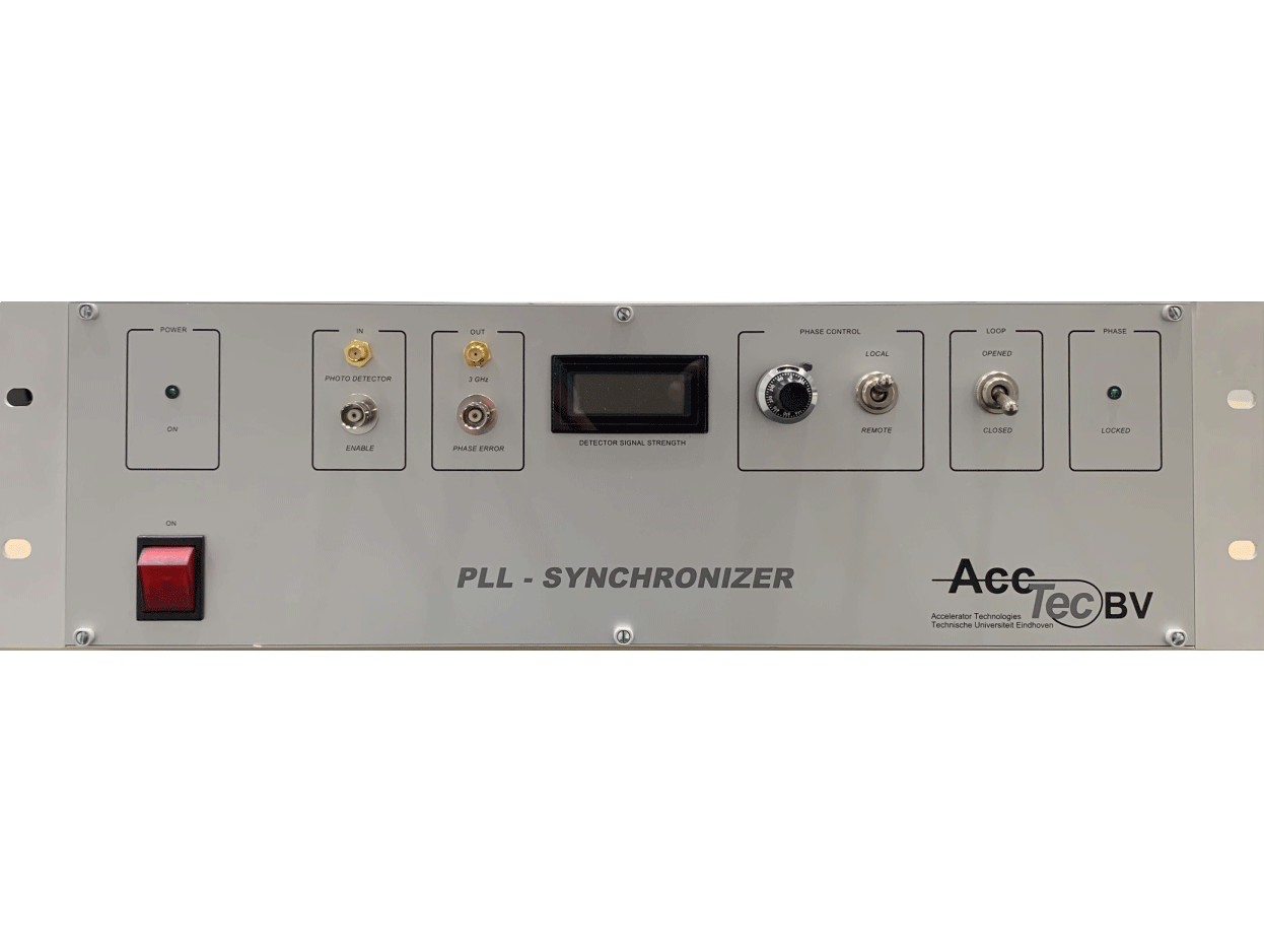
Synchronizer
To enable 100 fs temporal resolution, the RF phase of the chopping cavity has to be synchronized to within 100 fs with the femtosecond laser, which can be done with our Synchronizer. The synchronizer is designed to synchronize a 3 GHz RF oscillator to a mode-locked 75 MHz Ti:Sapphire laser system with less than 100 fs phase jitter.